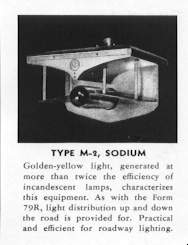
Type M-2 GE Low Pressure Sodium luminarie (circa 1938-1953)
General Information
During the late 1930s when mercury vapor lamps became commercially available, low-pressure sodium streetlighting was also introduced. Until high-pressure sodium arrived on the scene in 1965, low-pressure sodium lighting was referred to as "sodium" or "sodium vapor" illumination. Within this section, the early years of low pressure sodium streetlighting will be focused upon and acknowledged as "sodium vapor".
This illuminant was common in Europe and Great Britain prior to its adoption in the United States. General Electric was the most prominent (if not the only) manufacturer of sodium vapor lamps and streetlighting luminaries in this country. Sodium vapor lighting was very much state-of-the-art in its day on account of the light source's high luminous efficiency, which was about 50 lumens per watt. This attribute, along with long lamp life, made this light source ideal and economically practical for some streetlighting applications.
LPS lamps, like their other high intensity discharge light source relatives, have long lives. The 18, 35 and 55-watt lamps have an average rated life of 18,000 hours and the 90, 135 and 180 watt sources are rated at 16,000 hours.
One feature of the LPS lamp is the independence of starting voltage with respect to ambient temperature, which is significant in contrast with the operation of the mercury lamp. The starting voltage is largely determined by the mixture of neon and argon, which cannot be separated at any normal ambient temperature, as mercury can from the argon-mercury mixture in mercury lamps. Once started the lamp requires between 8 and 15 minutes, depending on type, to attain full light output and during this time the electrical characteristics change slightly. In some lamps a trace of xenon (0.2 percent) is added to the tube voltage for warm up. Unlike other high intensity discharge sources, LPS lamps are unaffected by momentary power supply dips or very short outages. They re-strike and come to full brightness almost instantaneously. With the increase of current in a LPS lamp the wattage increases slowly. As a result the peak of luminous efficacy is reached before the lamp reaches its maximum lumen output. The LPS lamp is designed to operate initially between the maximum output points, and that a slight increase in supply voltage will raise the light output but lowers the efficacy.
LPS lamps in general operate with a high reactance transformer or ballast, providing a high voltage for starting; in some cases this auxiliary equipment can be used for more than one lamp rating. In addition to standard customer distribution voltages, LPS lamps can and are operated from special 6.6-ampere street series isolation transformers designed for the appropriate lamp wattage. This auxiliary equipment is far less complicated than the early variety, which was utilized for the earlier types (NA-versions) of street series LPS lamps.
In addition to the lamp, external equipment was required for lamp operation and included the transformers, timer, etc. The main current or series transformer connected directly to the series circuit and its secondary, consisted of two copper lead-out wires with the series circuit film cutout placed between them. A capacitor and choke coil were incorporated in the circuit for radio noise suppression. Two autotransformers supplied proper voltage to the two filaments that were used to warm up the cathodes prior to starting the electric discharge. A timer or time-delay relay was used to energize the filament autotransformers for warm-up while the anodes were connected together and then, once the cathodes were hot, the timer opened the circuit between the anodes, allowing an inductive "kick" from the transformer to create the initial discharge. Typically, the preheating time varied but was usually under one minute. The timer was designed to instantly reset in case of a power failure. Different types of timers were developed, one type used with early LPS lamps having a special motor and instantaneous relay.
Upon startup, each cathode filament required 10 amperes exciting or heating current at 2 to 3 volts. After the preliminary heating of the barium-coated filament-electrodes (this coating helped provide for efficient emission of electrons), the short circuit caused by the timer was broken and the momentary high open-circuit voltage of the series transformer struck an arc in the neon gas between the electrodes and caused the lamp to first glow with the neon gas's characteristic red color. As soon as the inside of the bulb warmed up enough, the sodium particles begin to evaporate, and gradually over a 30-minute period the sodium vapor comes up to full brilliancy in its characteristic orange-yellow color. The instant resetting of the luminarie's timer in case of power interruption and the use of the film cutout, which short-circuited the secondary leads of the series transformer in case of lamp failure, provided proper safeguards for the lamp and series circuit.
The orange-yellow color of LPS light can be roughly observed by dropping common table salt (sodium chloride) into the gas flame of a kitchen range. This peculiar color is not particularly acceptable for general illumination purposes but has been suitable for highway lighting and other areas where levels of highly energy-efficient outdoors lighting where color rendition is unimportant. LPS lighting has also been found advantageous in fog-prone areas since the sodium light does not scatter. Incidentally, the curve of eye sensitivity to various wavelengths of light show visual sensitivity to be highest in the region of color of sodium light. Early LPS lamps provided about 50 to 55 lumens per watt, and even considering transformer losses; this was a very attractive feature of these lamps in their day. This was more than twice the efficacy of incandescent streetlighting lamps at the time.
The movement of sodium limits the permitted orientation of LPS lamps in operation. The metal will condense in the coolest region but vibration and gravity cause the molten sodium to fall to the lowest point. In U-shaped lamps, base down operation can result in lamp failures due to the sodium collecting behind the cathodes, causing electrolysis and cracked seals.
Base-up operation can result in sodium collecting in the bend and all but the shortest lamps will produce "red burners", caused by a shortage of sodium in the upper portion of the discharge tube. Lower wattage lamps can, with little light loss, be operated vertically base up. Modern integral U-shaped lamps can be operated within 20 degrees of horizontal and 15 degrees of base up for the 18, 35 and 55-watt lamps and only within 20 degrees of horizontal for those of 90, 135 and 180 watts.
The majority of these luminaries were designed for 6.6-ampere series operation, although a few were used on multiple circuits. Since they were installed widespread throughout the United States principally in series operation, only these will be discussed within this section.
Type M-2 GE Low Pressure Sodium luminarie (circa 1938-1953)
NA-9 Low Pressure Sodium Lamp
Early "Sodium Vapor" Streetlighting
Several sizes of sodium vapor lamps were made but only two were popular. These were the 180-watt, 10,000-lumen lamps that were the most widely used (known as the NA-9) and the 145-watt, 6000-lumen lamp. Their principal application was street and highway illumination and were employed in multiple and series operation luminaries.
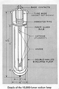
The overall length of the lamp, including the base, was about 16 inches. A small quantity of sodium and an additional amount of neon gas was placed within the bulb; the neon being used for starting. The double-walled evacuated flask (vacuum flask), similar in principle to an ordinary thermos bottle, was slipped over the lamp and held in place by means of an asbestos ring, which also acted as a stopper to prevent loss of heat.
The 10,000 lumen lamp consisted of a tubular inner bulb about 12 inches long and three inches in diameter placed within a double-walled flask to maintain proper temperature. The inner bulb contained a small amount of sodium, and some neon gas to facilitate starting. Coiled filaments at either end served as cathodes with one side of each filament connected to molybdenum anodes so that only four base contacts or pins were required at the socket. Therefore, each lamp had two cathodes and two anodes. Since each anode was connected to one end of each filament cathode, only two conductors lead from each assembly to the pin-base contacts. Molybdenum is one of the metals often used for contact points. The NA-9 consumed 180 watts while the smaller counterpart was rated 145 watts at 6000 lumens. Both had estimated life expectancies of 3000 hours under normal street or highway lighting service. The NA-9 lamp had a starting voltage of 50 and a normal operating voltage of 30 with a current rating of 6.6 amperes. A photograph and illustration of the NA-9 lamp is included within this section. On starting, a time-delay relay in the luminarie housing allowed the cathodes to heat. Then the circuit was broken and an inductive kick of the ballast started a discharge of neon with its characteristic red color. As the temperature rose, the sodium vapor came up to full brilliancy and color. This required about 30 minutes. The 10,000-lumen lamp had an average life of 4000 hours as of the late 1940s, when utilized for streetlighting service. The lamp required 50 volts to start and progressively dropped down to 30 volts as the lamp fully warmed up. Its current rating was 6.6 amperes.
The auxiliary equipment for series operation of the 10,000-lumen lamp consisted of a time-delay switch arrangement that pre-heated the cathodes and a radio interference suppressor. For operation on multiple circuits a reactive ballast was also provided since the supply circuit did not regulate the current as was the case with series operation.
These lamps were utilized in a specially designed fixture produced by General Electric (shown above). The luminaries were odd looking, with the lamp and its exterior flask exposed in the fixture's center. A curved, polished aluminum reflector on each side of the protruding lamp was designed so that there was sufficient illumination of the roadway for an adequate distance from both sides of the fixture. Auxiliary equipment was contained within a box-like compartment area behind the lamp's socket. The four male prongs mounted on the lamp's Bakelite base mated with a receptacle in the luminarie.
In addition to General Electric's winged, boxy shaped sodium vapor fixtures, their NA-9 sodium lamps were also utilized within standard pendant style glass globe luminaries and within post-top ornamental streetlighting fixtures. The manufacturer incorporated the necessary auxiliary equipment required for lamp operation into these fixtures.
The General Electric Form M-2 luminarie was specially produced for their early LPS lamps and consisted of a specially curved "airplane winged" reflector on each side of the lamp. These reflectors were made of aluminum, finished by an electrochemical process that gave a reflecting surface with a coefficient of reflection of approximately 80 percent. The upper curved parabolic reflectors and the flat surfaces suspended below were specially positioned in order to give the wide angle of light distribution necessary for highway lighting. This reflecting unit was actually called an airplane type of reflector in its day because the upper and lower reflecting surfaces resembled the wings of a biplane. A small triangular section of reflector installed just below the lamp was to prevent too much light from being directed immediately below the luminarie, allowing the light to be spread more uniformly. A housing in the rear of the fixture contained the auxiliary equipment such as the autotransformers, timer, etc. Since the entire length of the bulb became luminous, the lamp burned horizontally, suggesting the use of a trough-like section of parabolic reflector with auxiliary plane-reflectors for efficiently directing the light to the street surface. The lamp and vacuum flask were inserted or removed from the rear of the luminarie. A holder that was bolted to the lamp housing supported the flask, and additional supports were also provided at the outer end of the flask.
The large luminous area of the LPS source was not so controllable by reflecting equipment in designing a specified beam pattern or light distribution, as the incandescent lamp easily allowed. For this reason it was often possible to deliver on the pavement surface acceptable lumens per watt from high efficiency incandescent highway fixtures and thus achieving higher visibility upon streets and highways, compared to just utilizing LPS lamps on a system. Thus, the LPS luminaries alone were found to be best applied on the wider three and four-lane highways of the time.
Most sodium vapor luminaries were installed along highways and on bridges. The color, appearance and quality of light provided by these early lamps are identical to present day low-pressure sodium lamps. That is, the illumination provided is monochromatic yellow, making objects appear yellow or mostly undistinguishable in color. Due to this drawback, sodium vapor streetlighting was limited to applications where such color distortion was not objectionable. These lamps were particularly advantageous in fog-prone areas because low-pressure sodium illumination does not "scatter" light as other illuminants do at night. Therefore, coastal and bridge installations were ideal for this light source.
Sodium vapor was part of standard streetlighting practice until about the mid-1950s. About that time mercury vapor lamps were becoming more practical and nearly as energy efficient as the sodium vapor ones. Mercury streetlighting luminaries were smaller, the lamps provided far better color rendition, lasted longer, took much less time to come to full brightness and permitted superior light control. General Electric produced replacement NA-9 lamps until 1966 or so. It is not known when they discontinued manufacture of their sodium vapor luminaries, however it is probable this occurred during the mid to late 1950s as the company was highly promoting the merits of their mercury vapor streetlighting fixtures.
Modern Low Pressure Sodium Lighting
Low pressure sodium (LPS) streetlighting did not reappear until the mid-1970s, evidently in response to very high lamp efficiencies that had been developed (typically 100 or more lumens per watt) and the 1974 Arab oil embargo which significantly increased electricity costs in most portions of the United States. As in this light source's earlier years, LPS streetlighting had been and continued to be limited where color rendering was not a significant factor. Because of decreasing high-pressure sodium (HPS) lamp and associated luminarie costs, LPS installations became competitive with HPS through the late 1970s and following years. In addition, HPS lamp efficiencies comparable to LPS added to this situation. However, a significant number of LPS streetlights are in operation as of 1998 and some utilities continue to install them. The 18, 35 and 55 watt LPS lamps have been commonplace since the late 1970s and have typically been utilized in luminaries that are of the standard NEMA head design with an integral ballast, photoelectric lighting control receptacle and latch-on optical assembly. Many of these fixtures have been used for security and area lighting also. Larger LPS lamps (55 through 180 watts) have been and are employed in elongated luminaries mounted upon longer bracket arms.
In order to effectively deal with a long arc tube a range of lamps are made where their arc tubes are bent back on themselves in the form of a tight, U-shaped tube. Further, conservation of heat loss is obtained in this case by mutual heating of these straight sections of the "U".
The U-shaped LPS lamp has a single bayonet base, referred to as the B22d type. Lamp wattage is changed by length and changes in the infrared coating on the lamps' outer envelope. The smaller lamps (18 through 55 watts) have a T-16 (2-inch diameter) outer bulb while their larger counterparts (90 through 180 watts) are manufactured with a T-21 bulb, (2.62 inches diameter).
An electrode is required at each end of the lamp to support the discharge, like the early version. These electrodes may take different forms in order to suit different lamp designs, but all basically employ fine tungsten wire coiled or woven into a form suitable for holding a quantity of alkaline earth oxides which are electron emitters when heated. During lamp operation the electrodes are heated by electron bombardment when it acts as a cathode.
Sodium metal is solid below 98 degrees C and has a low vapor pressure. It is therefore necessary to use an inert gas filling in the arc tube to start the lamp and allow it to attain operating temperature. As with the early LPS lamps, neon is used for this purpose. It is usual to include up to one percent argon with the neon in order to assist starting the arc. The argon produces a mixture that lowers the starting voltage requirement by as much as 50 percent in some designs.
Sodium vapor is very reactive at elevated temperatures and chemically attacks most types of glass. A special glass type has been developed to resist this attack but it is expensive and difficult to work with. Therefore, a less expensive and much more workable soda-lime glass with a special coating on the inside is used. The resulting glass is sometimes called "ply tubing" and is used in the manufacture of all types of LPS lamps. Besides being chemically very active at high temperatures, sodium vapor is readily transported through porous material by electrolysis. Special care has therefore to be taken in mounting the arc tube inside the outer envelope. Ceramic insulators are necessary for holding the ends of the U-shaped arc tubes in a mounting frame, and care must also be taken to isolate the infrared reflective coating of tin oxide, indium oxide or gold which is quite conductive. It also is necessary to use a very high sensitivity glass around the lead wires to prevent concentration of electrolyzed sodium at the glass to metal interface, which may cause cracked seals.
It took many years to develop sodium-resistant glass types that did not discolor with sodium attack and still longer to reduce the tendency of these glass variations to absorb argon at low filling pressures. Glass used today in manufacturing LPS lamps does not discolor and permit neon-argon filling pressures of specified amounts. The modern U-shaped LPS lamp employs a large diameter arc tube and is filled at a low gas pressure.
A lamp of reduced wattage requires better heat retention compared to larger types to maintain the sodium vapor pressure, and it is necessary to seal the arc tube of all lamps in an outer jacket with a high degree of vacuum. Heat loss is almost entirely by radiation and coating the outer jacket with tin or indium oxide can reduce this. These oxides are reasonably transparent to the light from the arc tube and can be made to reflect a high percentage of its infrared radiation. Improvements in these infrared reflective coatings are a possible source of reduced energy requirements for the same lumen output in all types of LPS lamps.
The maintenance of lamp efficacy during life is assisted by the provision of small round protrusions on the outside of each arc tube side which, because they are slightly cooler than the remainder of the arc tube, act as reservoirs for sodium metal. Here, the metal is retained against possible temperature gradients and mechanical shock or vibration which can result in a loss of sodium and therefore of its vapor pressure at points along the arc tube.
Continue to the Fluorescent Lamps page or return to main page