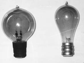
Thomson-Houston base lamps - series bulb on left (ca.1895), household bulb on right (ca.1900)
Tungsten-Coiled Series Streetlighting Lamps
By about 1912 or so, gas-filled tungsten filament incandescent lamps were introduced and were a huge improvement over their carbon filament predecessors. With the advent of the "Mazda C" tungsten lamps, the lower light output (such as the 32 through 100 candlepower lamps) were manufactured with much smaller filaments than the older carbon-filament units. These new incandescents meant whiter light and improved lamp life for secondary roadway installations as well. This new style incandescent lamp provided much better light output efficiency for all types of filament lighting service and they lasted much longer. These tungsten filaments were coiled; somewhat like today's and for street lighting purposes they were a blessing. These incandescents were much less costly to maintain and provided a steady light output (arc lights were known to flicker). These were readily available with small sized filaments, which provided just as nice a light output as their arc light counterparts and at much lower cost. Thus, the gas-filled, tungsten-filament streetlighting lamps rapidly became the choice for street illumination beginning in the teens, gradually replacing all of the old arc light fixtures.
Of interest, several styles of series streetlighting lamps are photographed and illustrated. The earliest is a carbon filament lamp designed to operate on a 3.8-ampere series streetlighting system. This circa 1895 lamp has a "Thomson-Houston" screw base, which is quite a bit different than the Edison screw base that is still manufactured to this day. Up until 1900 a variety of incandescent lamp bases were utilized and manufactured in the United States. However, after then, the Edison screw base eventually won out as the standard for household, commercial and streetlighting applications. While the smaller sizes were produced with "Edison" (medium size) bases, the larger wattage and practically all street series lamps have since been manufactured with a larger screw base, known as the "mogul" size. Also illustrated are various bulb shapes and light output sizes of street series lamps produced through the years. Incandescent lamps produced in this country for most lighting applications were made without the vacuum tip on their ends after about 1915.
Series Streetlighting Lamp Evolution
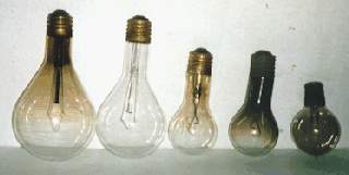
As previously mentioned, prior to 1900 incandescent lamps utilized in the United States were manufactured with a variety of socket and base configurations. After the turn of the century the Edison screw-base became the industry standard, gradually making all of the prior lamp base designs obsolete. This was also true with streetlighting lamps; after 1900 most had screw bases and were of the larger or "mogul" screw thread type, like seen on today's high wattage incandescents. Up until the inception of the tungsten filament lamps around 1912 outer bulbs for streetlighting applications varied. Some of these carbon filament lamps had the old familiar; straight sided "pear shape" design and others were globular or rounded in appearance. When the gas-filled, coiled tungsten lamps came on the scene during circa 1912-1916 series streetlighting lamps typically were of the S-24-1/2 design for lamps 100 candlepower (1000 lumens) and under. (See photo). Higher output series lamps were then made with rounded, pear-shaped outer bulbs. For instance, PS-35 bulbs were used for 2,500 and 4,000 lumen lamps and PS-40 bulbs for 6000 lumen and higher output lamps. PS-52 bulbs were made for the rarely required 20,000 and 25,000 lumen series lamps.
Generally after the 1920's there was little requirement for series lamps with light output below 1000 lumens; however up until the late 1970's Sylvania was still producing series lamps in the 320, 600 and 800 lumen output sizes. Of note, series and multiple streetlighting incandescent lamps have always been rated in terms of light output instead of watts. Beginning in the 1930's and 1940's most lamp manufacturers began listing their lamps in lumens, instead of candlepower (1 candlepower equals approximately 10 lumens). Wattage and voltage ratings that are typically used to designate multiple lamps have not been commonly used with series lamps - instead, the lumen output and amperage ratings are specified. For example, a 6000 lumen, 6.6 ampere lamp or a 15,000 lumen, 20 ampere lamp. Though series lamps as small in output as 250 lumens were available, the standard sizes ranged from 1000 lumens to 25,000 lumens. Multiple lamps are designed for a specific wattage and voltage and changes in efficacy are evident by changes in lumen output. The lumen output of series lamps, on the other hand, remains fixed because the lumen output is generally specified by local community governments and changes in efficacy due to improvements are reflected by changes in wattage or voltage. This usually results in odd numbers and fractions. For example, a 6,000 lumen, 6.6 ampere, 2,000-hour life lamp has an average rating of 48.6 volts and 320.9 watts. On a constant current circuit the filaments for all sizes of lamps of a given circuit rating are approximately the same diameter but of different length. The lamp voltage will vary with the lumen output, ranging from a few volts in the smaller sizes to 50 to 60 volts for lamps of high lumen ratings.
By the 1930s, the S-24 1/2 bulb design (used on the 320 lumen through 1,000 lumen lamps) was replaced by the PS-25 design (same shape as a modern mogul-base three-way household light bulb). This new design for street series lamps continued unchanged until about 1990 when 1,000 lumen series lamps were discontinued. When the PS-35 series lamps (same shape as a modern 300-watt 120-volt incandescent) and slightly larger PS-40 series lamps (same shape as a 120-volt, 500-watt incandescent) were introduced they remained essentially unchanged physically and in filament design through the years. As of 1998 only one manufacturer was producing series lamps in the 2500-lumen size; all other larger incandescent lamp companies have either stopped making series streetlighting lamps or have downsized their offerings to only the 4000 and 6000 lumen sizes. It will truly be a sad day in streetlighting history when series-operation incandescent lamps are no longer made by anyone! However, that day is inevitable because utilities are finding that their aging series circuits are becoming more expensive to maintain and energy and operating costs can be reduced substantially by switching to high-intensity discharge light sources. Although series incandescent systems are rare and very widely scattered throughout the United States, the vast majority of them still in existence are concentrated in the greater Los Angeles, California vicinity.
Thomson-Houston base lamps - series bulb on left (ca.1895), household bulb on right (ca.1900)
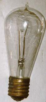
1000 lumen, S-24-1/2, 6.6 ampere series streetlighting lamp ca.1915

Series and multiple incandescent street lighting lamps
Street series lamps
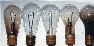
1930s series streetlighting lamps
Street series lamps are designed to operate in series on most constant current circuits. A typical constant-current circuit had a special transformer with a movable, counterbalanced secondary that provided a constant current (usually 6.6 amperes) output regardless of how many lamps were in the circuit or their lumen rating. There were also lamps designed for 15 and 20-ampere operation, and these were run off isolation transformers that were wired into the main series lighting circuit. These transformers, known as the "IL" type, stepped up the lower amperage of the main circuit to the amperage required by the lamp. There were several advantages by using these isolation transformers. First of all, they provided safety by insulating the pole and fixture from the high voltage series circuit, allowing more conventional wiring between the transformer and lamp socket, particularly with pendant and bracket fixtures mounted on metal poles. The transformers also permitted the use of high-current, high efficiency, concentrated filament series lamps, which were desirable because of the quality of the light and for use with redirecting glassware. They protected the lamps from surges in the line; allowed the use of low voltage cable in poles and eliminated the necessity for film cutouts, both of which usually offset the additional cost of the IL transformer. These transformers also eliminated about 75 percent of all series circuit line troubles which were known to occur between the transformer secondary leads and the fixture.
Design Features
Series street lighting involved special lamp construction features. Lamps had to withstand extremes of temperature and weather, vibration and shocks of heavy road traffic and finally their design involved the problem of conducting heavy current to the filament. In straight series operation, provisions were required for protection against arcing at time of lamp failure when the voltage between the lead wires approaches several hundred volts or higher. A film cutout that punctures under this high voltage has been necessary for each lamp socket. Additional safety features are built into the smaller lamps to protect the socket from an arc that may take place within the lamp when it fails. Unless addressed by proper protection, an arc thus created may travel up the socket, welding the socket and lamp base together and perhaps even destroying the socket.
Heavy nickel lead or support wires have been used in lamps, the filament ends wound with tungsten wire to add strength against vibration. "Close lead" construction, which means bringing the lead wires closer together, is used in the smaller sizes - since the lamp has a low operating voltage, if the film cutout does not puncture right away, an arc develops between the lead wires, fusing them together at their closest point, completing the circuit before the arc has a chance to cause damage in the socket.
The improvements in quality and uniformity of filaments used in street series lamps have, interestingly, introduced some disturbing results in street lighting service in prior years. Formerly, most filaments failed "cold"; road vibration and shock taking a toll by jiggling the filament apart at its weakest point. Such failures were identified by a clean break. There were some known as "hot" failures; that is, occurring during burning hours and can be identified by globules of melted tungsten at the point of parting. In many cases due to the peculiarity of the high voltage series circuit, welds in the filament were likely to occur at the point of failure due to the high circuit voltage. Such welds have been known to occur many times with the result that the lamp may not actually fail but continue burning. In such a case the effective filament length is so short (since each weld reduces the effective filament length) that in extreme instances light output has reduced to perhaps a quarter or less of the initial value. For example, a 10,000-lumen lamp with ten such filament welds might provide the light output equivalent of perhaps of a 1000 or 2500 lumen lamp. Such lamps have been known as "slumpers" though in a way their virtues may have been said to become faults. Typically these lamps have blackened quite significantly and sometimes severely in their uppermost portion due to excessive tungsten evaporation. In extreme cases, they have been detected by their reduced light and reddish color in comparison with other neighboring lamps on the circuit. Group replacement was a way to eliminate these "slumpers" before they became too obvious.
Depreciation During Life
The light output of a series lamp operated at rated constant current changes very little during life. The filament, evaporating and becoming smaller as the lamp is burned, gradually increases in resistance requiring a rise in voltage to maintain a constant value of the current. This in turn increases the wattage and filament temperature causing an increase both in efficacy and lumens provided by the filament. The increased lumens from the filament may eventually be offset by the light absorption due to bulb blackening. The actual net changes in lumen output will vary with relative bulb size, shape and burning position.
The increase in voltage and wattage of lamps on series circuits will amount to about 4 percent above the initial at the end of their rated life, averaging about two percent during life. Provision has had to be made in the capacity of constant current transformers for this increase in voltage.
Pioneer series streetlight systems
Soon after Thomas Alva Edison invented the incandescent lamp in 1879, illumination of public ways in the United States using incandescent lamps became commonplace as electric lighting plants sprung up all over the country, especially by the 1890s. Such early incandescent streetlighting fixtures were commonly pole-mounted and of the "gooseneck" type using 3/4" pipe and which extended 4 feet out from the pole. Other installations, although not so frequent, used similar incandescent fixtures mounted on span wires over intersections. Most of these "double-walled" luminaries had a conical reflector, hollow inside with a copper or galvanized steel top and white porcelain enameled reflecting surface separately attached underneath (often held in place with tabs). Many of these reflectors offered through the years had a smooth surfaced underside instead of a grooved or radial wave configuration. An early example of this type of fixture with an inverted-cone reflector is shown in the "My Collection" page on this website. Some vintage catalog cuts showing this type of fixture are shown in the "Catalog" pages. The fixture shown in the "My Collection" page is circa 1900 and was removed from its gooseneck style pipe. This luminarie design continued approximately 1912-1915 when porcelain style fixture heads were introduced. Typically, the earlier conical, double-walled reflectors were 14 inches in diameter; those used on porcelain fixture heads were 18 or 20 inches and most were stamped from a single sheet of steel instead of being constructed from two separate sections. All pre-1940 porcelain heads utilized radial wave reflectors and had white porcelain on their reflecting undersides and the earliest (1912-1920) were dark blue enameled on top. Reflectors produced after 1920 usually had either green or light gray porcelain enamel on top. Generally, the color of the reflectors' topside had much to do with customer preference and who made them.
Porcelain Head Series Fixtures
Porcelain fixture heads were better able to handle the series circuits' high open-circuit voltages than their predecessors and typically were made of either wet- or dry-process porcelain with black, brown, grayish or green glazes (the latter being most common). The fixtures were affixed to 3/4 or 1-1/4-inch diameter pipe brackets; many of which were very ornately designed. Through the years various porcelain head fixture and radial wave reflector configurations evolved; most of this evolution was in response to customer requirements; i.e., series circuit voltages employed and the manner of light distribution desired. Porcelain fixture heads were produced until the early 1960s, little changed from the first ones introduced 50 years earlier. Many of the radial wave porcelain enameled reflectors mounted upon these fixtures also remained pretty much unchanged. Since many of the larger electrical utility supply houses (i.e., General Electric, Joslyn, Line Materials, Westinghouse, Pemco and others) offered series operation streetlighting luminaries there was a lot of variation in design; some companies offered more styles and options than their competition so a wealth of series streetlighting fixtures were made through the years. Adding to this great assortment were the higher lumen output luminaries that could be ordered with any of numerous reflector and globe combinations. Some samples are photographed and illustrated within this website.
Most of the earliest incandescent streetlighting fixtures employed lower light output lamps and were utilized along secondary roadways. The most common size of series streetlighting bulbs at the time was 32-candlepower. Higher light output lamps were available but they were far more expensive. These were installed in business districts, town centers and at busy and/or dangerous intersections. Usually, though the practice through the early 1910's was to install arc light fixtures, where increased illumination was required, but this would change.
The Basics of Series Incandescent Streetlighting Operation
Early-day streetlighting installations operated mostly on series circuits; the most common was 6.6 amperes, although other amperages such as 3.8, 5.5, 7.5, 15 and 20 were utilized. In the early days arc lights were often intermingled with series incandescent lamps. Electrically, it made no difference what the light source was as long as all luminaries within the series loop required the identical amount of amperes to operate properly. The variable electrical factor was the number of volts required for fixture operation; obviously, more volts were needed for lights providing more illumination and vice-versa. Originally, the central station attendant regulated the proper amount of voltage supplied to the system. With series systems, absolute constant current (i.e., 6.6, 15, or 20 amperes, etc.) throughout the streetlighting loop is critical. The amount of volts required for a given system is the total of all lamps/fixtures combined. Thus, a 6.6 ampere series system having 50- 1000 lumen lamps (each lamp requiring 12 volts); 25- 2500 lumen lamps (25 volts each) and 10- 4000 lumen lamps (35 volts each) would require a total of 600 volts for the 1000 lumen lamps; 625 for the 2500 lumen lamps and 350 volts for the 4000 lumen ones for a total required circuit voltage of 1,575 volts. The high voltage required for series streetlighting circuits was supplied directly from a primary distribution circuit connected to the constant-current regulator. The amount of volts necessary for proper individual lamp or fixture operation was published information from the manufacturer. In simpler terms, series streetlighting circuits are just like a string of miniature Christmas tree lights. One wire ran into one lamp and out to the next. This simple configuration requires only one wire running from pole to pole. A "break" or separation insulation insulator was utilized to "dead-end" or terminate each side of the series line wire so that the two fixture leads would extend to the fixture, this insulator being in line with the wire or mounted on a crossarm.
Among the major advantages of series streetlighting was the simplicity of design as described earlier. Thus, only one wire was required to operate all of the streetlights on the circuit. Another advantage was savings in copper wire that had to be strung. It was, and is with existing series streetlighting circuits that constant continuity must occur between the beginning and end of any series loop; a break anywhere in the wire would cause all of the lights in the circuit to extinguish until the repair was made. Burned out lamps do not affect circuit continuity because provisions were made in series lamp sockets so that a defective lamp is electrically bypassed. In the earliest days of streetlighting a small piece of mica was inserted at the base of the lamp or within the receptacle that burned through instantaneously when the lamp failed. By the early teens and continuing to the present series incandescent socket design uniformly employs a wafer like, dime sized "cutout" button that is inserted between the series lamp's two socket prongs, providing similar or better continuity protection. Thus, when the lamp was broken or burned out, the series "cutout" between the two tightly fitting socket prongs in the mating receptacle head would simply burn through or electrically puncture, assuring that all other series incandescents within the loop operated without any disruption. Incandescent series fixtures were designed so that when their porcelain or Bakelite sockets were extracted from the luminarie that the receiving or mating receptacle prongs inside the fixture would instantly make contact as the socket was withdrawn from the luminarie. Also, most series sockets were designed so that their center tab came instantly in electrical and physical contact with the socket's screw threading when a lamp was unscrewed from the socket. Those series sockets that did not have this feature (and they were few) relied upon the button cutout to shunt through. So, as you can visualize, series incandescent luminaries were designed to be fail-safe, assuring absolute electrical continuity whenever a lamp failed or was being replaced. Such fixtures had to be made to withstand very high open circuit voltages when a break in the circuit took place. During such outages, the series regulator would (and present ones still do, unless an automatic de-energizing device is present) produce open circuit potentials of 5,000 volts or more. Therefore, it always was and still is important that ALL series fixture electrical components be adequately insulated to prevent electrical flashovers within the luminaries during live open circuit outages. Hence, many series incandescent streetlighting heads were made of porcelain and the later aluminum or metal cased ones had heavy duty, high voltage rated porcelain receptacles with adequately sized porcelain entrance bushings (like those used on distribution transformers).
Series Streetlighting Controls Employed Through the Years
In the early days series circuits were manually controlled at the central station. The operator would adjust the voltage required for each series loop, also assuring that a specified amount of constant amperage was delivered to operate all of the fights in the system or "string". The streetlighting operator would also turn the system(s) on at dusk and off at the appropriate time. Up until 1920 or so it was commonplace for many communities to operate their streetlighting circuits on what was known as the "moonlight schedule". That meant during clear evenings where the moon was full or nearly full streetlighting systems were purposely not put into operation because of the "adequate" amount of natural illumination provided by moonlight. Also, depending upon the agreements made with each community, series circuits were shut off during late hours, typically about midnight or 1 AM. This practice was pretty much discontinued by the 1920's although some of the more rural and various suburban communities in the United States continued to shut off their streetlight systems in the late evening series for some decades later. Major factors influencing such decisions of streetlighting operating hours were safety factors and operating cost/maintenance expenses. In most cases, the general public and town fathers decided how long they wanted their streets lit each evening. Starting in the 1930's series streetlighting systems became automated by the use of constant current transformers, which assured proper voltage and amperage throughout each series loop. Many older linemen refer to these regulators as "tubs" due to their size over regular transformers. Also, time and duration of operation was made simplified by photoelectric controls or time switches. Some of the latter were designed to advance or deduct a minute each day- so that the series circuits were activated just about dusk and de-energized at daybreak. These were known as astronomical time switches and became quite popular until the cost of photocontrols became more affordable. A standard operation time switch wired after the photocontrol or astronomical time switch provided automatic system shutoff at a preset time. On my Incandescent Streetlighting page is a 1990 photograph of a utility pole completely outfitted with an automatic series incandescent system regulator, oil switch, photoelectric lighting control and glass-enclosed automatic time switch. The latter are on the lower crossarm if you look closely. Each is contained in an enclosure similar to that of an electric meter and are mounted in meter sockets. The regulator pole in that photograph operated a string of about ninety 1,000 lumen series streetlighting lamps (now removed) and the time switch was wired AFTER the photoelectric lighting control, making this installation probably the last late-evening series streetlighting system in the country!
Series Circuit Characteristics
Series circuits require close regulation as fluctuations from normal current will cause variation in lamp performance. The effect of current variation in series circuit operation is considerably greater than voltage variation on multiple operation. Roughly, a one percent change in amperes (0.066 of an ampere on a 6.6 ampere circuit) will produce about a 1.75% change in volts; about a 2.75% change in watts; about a 3.5% change in efficacy; and a 7% change in light output.
The fate of most series lighting circuits
As the demand for photoelectric lighting controls increased during the 1950's and the cost of them continued to decrease utility companies began to replace their aging series streetlighting systems with multiple operation luminaries. This trend became the rage in the United States especially during the 1960's. Combining the advantage of individual, low-cost streetlighting control and the increasingly popular energy-efficient mercury vapor lamps that also were becoming more affordable, a great many series systems were removed by the late 1960's. Most of the few series systems that remained were upgraded to multiple incandescent or high intensity discharge operation light source luminaries through the 1970's, although a large number of series circuits continue to be operated in the Los Angeles, CA area with a variety of light sources on the circuits.
Continue to the Incandescent Multiple Lamps page or return to main page